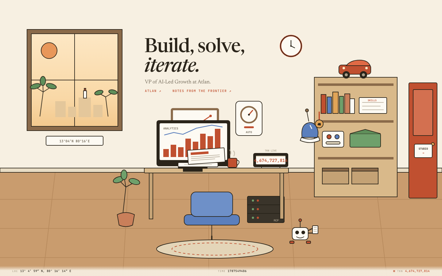
During a recent weekend build session using Z.ai's ZCode harness and GLM-5.3, we set out to build a fully illustrated, interactive homepage for surendranb.com. The brief was direct: instead of another standard portfolio of card grids and text blocks, build an authentic virtual studio room representing my workspace in Chennai.
The initial zero-shot attempt failed catastrophically. The output looked like a three-year-old's scribble: desks floating in mid-air, plant leaves slicing through window panes, an arbitrary speedometer hovering next to a monitor displaying a cartoon bar chart, and zero physical grounding.
When prompted with traditional graphic design feedback—"use a tri-zone layout", "apply uniform 3px stroke weights", "reduce object count"—the visual style cleaned up, but the room refused to appear.
The breakthrough came only when we completely abandoned aesthetic prompting and treated the SVG as a physical construction site.
LLMs possess exceptional formal linguistic competence (valid SVG syntax, tags, and CSS) but zero functional world models (spatial physics, containment, and metric grounding). If you want an LLM to generate believable spatial structures, do not give it adjectives. Give it a coordinate frame, an origin point, and the causal sequence of the physical world.
1. The Core Failure: The LLM Spatial Reasoning Deficit
To understand why LLMs fail at spatial generation, we have to look at the mathematical mechanics of autoregressive token prediction.
Text Sequence (1D):  w_1 → w_2 → w_3 → ... → w_t ~ P(w_t | w_<t)
Canvas Space (2D):   (x, y, width, height, z-index, occlusion, lighting)
A. 1D Next-Token Prediction vs. 2D Euclidean Space
Autoregressive transformers compute a probability distribution over the next token w_t conditioned on the preceding linear string w_<t. They do not maintain an internal 2D Euclidean coordinate matrix or a physics simulator in latent memory.
When generating vector markup like SVG (<rect x="240" y="380" ... />), the model does not "see" the coordinate intersection or check whether y="380" collides with an existing object. It samples statistically plausible integers that frequently co-occur near SVG attributes in its training corpus. The result is blind coordinate sampling: valid XML syntax that represents an impossible geometric state.
B. Formal vs. Functional Linguistic Competence
In their seminal 2024 paper (Trends in Cognitive Sciences), Mahowald, Ivanova, et al. established the formal dissociation between:
- Formal Competence: Mastery of syntax, grammatical structure, and tag validity.
- Functional Competence: World knowledge, commonsense reasoning, intuitive physics, and situation modeling.
LLMs possess exceptional formal competence. In Version 1, the model generated valid SVG XML with perfect tags, hex colors, and CSS attributes. But it possessed zero functional competence: it had no conceptual model that a heavy wooden table requires a floor plane to rest upon, or that a mug must occupy the coordinate plane directly above the table's surface.
C. Rich Sutton's "Quarter of Intelligence" & The Big World Hypothesis
On the Training Data podcast, reinforcement learning pioneer Rich Sutton and Khurram Javed discussed why static, pre-trained LLMs hit a reasoning ceiling. Sutton pointed out that current LLMs represent approximately a quarter of intelligence—the linguistic pattern-matching quarter.
The missing 75% comprises:
- Continuous State Representation: Tracking the geometric state of the environment.
- Perception Loops: Seeing the rendered output of an action.
- Physical Grounding: Understanding invariant physical laws (gravity, light, containment).
2. The Architectural Unlock: Scale First (288px = 1.00m)
The initial instinct in web development is to use relative percentages or flexible viewports. For spatial AI generation, this guarantees coordinate drift.
We solved the spatial deficit by introducing a rigid Metric Grounding Prior:
288px = 1.00 metre (on a 1440 × 900 canvas)
On our standard 1440 × 900 (16:10) desktop canvas, with the floor plane datum locked at y = 720px, all spatial geometry immediately collapsed into simple, deterministic arithmetic:
y_object = 720 − (Physical Height in Metres × 288)
y = 0px   ┌────────────────────────────────────────────────────────────┐  ▲
          │  CEILING DATUM (2.50m from floor)                          │  │
y = 144px │  · Wall Clock Center (2.00m)                               │  │
y = 156px │  · Studio Door Top (1.96m)                                 │  │
y = 288px │  · Human Eye Level & Thermostat (1.50m)                    │  │ 2.50m
y = 440px │  · Window Sill Height (0.97m)                              │  │ WALL PLANE
y = 504px │  · Work Desk Surface (0.75m / 75cm)                        │  │ (720px)
y = 590px │  · Task Chair Seat (0.45m / 45cm)                          │  │
y = 720px ├────────────────────────────────────────────────────────────┤  ▼
          │  FOREGROUND FLOOR PERSPECTIVE (0.625m depth)               │  180px
y = 900px └────────────────────────────────────────────────────────────┘
Why 288 is the Master Architectural Ratio
| Metric Dimension | Real Metric Height | Derived Offset | Calculated SVG $y$ | Architectural Purpose |
|---|---|---|---|---|
| Room Ceiling | 2.50 m (8.2 ft) |
720 px |
y = 0 px |
Universal residential ceiling height |
| Wall Clock | 2.00 m |
576 px |
y = 144 px |
Above eye level; divisible by 12 & 16 |
| Studio Door Frame | 1.96 m |
564 px |
y = 156 px |
Standard architectural door clearance |
| Eye Level / Thermostat | 1.50 m (5.0 ft) |
432 px |
y = 288 px |
Human optical baseline (1m below ceiling) |
| Window Sill | 0.97 m |
280 px |
y = 440 px |
Standard sill height |
| Work Desk Surface | 0.75 m (75 cm) |
216 px |
y = 504 px |
ISO standard ergonomic desk plane |
| Task Chair Seat | 0.45 m (45 cm) |
130 px |
y = 590 px |
Leaves 86px ≈ 30cm knee clearance |
| Floor Datum | 0.00 m |
0 px |
y = 720 px |
Gravity baseline for all standing objects |
288 is a highly composite integer with 16 divisors (2, 3, 4, 6, 8, 9, 12, 16, 18, 24, 32, 36, 48, 72, 96, 144). Metric fractions (½m = 144px, ¼m = 72px, ⅛m = 36px, 1/12m = 24px) evaluate to exact whole integers, eliminating sub-pixel antialiasing blur on standard and Retina displays.
3. The Visual Evolution: Interactive Storyboard
Below is the step-by-step visual progression from the authentic Version 1 scribble through all 8 construction phases and the 4 dynamic solar sky states.
4. The Causal DAG: Construction Order = Paint Order = Z-Index
In 2D vector graphics, rendering follows the Painter's Algorithm: elements defined later in the DOM overwrite elements defined earlier.
When an unconstrained LLM generates SVG code, it emits objects arbitrarily. If it emits the coffee mug before the desk, or the window frame after the sunlight shaft, the visual graph breaks.
We forced the LLM into a strictly ordered, topologically sorted Directed Acyclic Graph (DAG) mirroring real-world building construction:
[Phase 1: Shell]  ──────► [Phase 2: Window] ──────► [Phase 3: Fixtures]
  (Wall/Floor/Trim)         (Cut into Wall)           (Mounted on Wall)
                                                             │
[Phase 6: Cabinetry] ◄─── [Phase 5: Furniture] ◄─── [Phase 4: Light]
  (Bookshelf & Books)       (Desk/Rack/Door)          (Ground Shadow Shaft)
        │
        ▼
[Phase 7: Occlusion] ────► [Phase 8: Foreground]
  (Drop Shadows)            (Chair/Rug/Sensor Robot)
The 8 Construction Phases
- Phase 1 — Shell (Wall, Floor, Baseboard): The static architectural envelope (
y=0toy=720wall,y=720toy=900floor, 13px baseboard trim). - Phase 2 — Window Cut into Wall: Fenestration geometry cut into the plaster, establishing the boundary between interior room space and outside world space.
- Phase 3 — Wall Fixtures: Objects anchored to the wall substrate (gallery motto art, milestone growth chart, clock at
y=144, marathon medal hook). - Phase 4 — Ground Shadows & Light Shaft: Global light projection cast across the floor plane before standing furniture is placed.
- Phase 5 — Standing Furniture: Heavy load-bearing structures resting on the floor datum (
y=720): work desk, server rack, studio door frame. - Phase 6 — Architectural Millwork (The Library): Bookshelf constructed with proper cabinetry joinery (plinth base, vertical stiles, crown molding) populated by project volumes using the
60/40vertical-to-horizontal stacking rule. - Phase 7 — Wall-Adjacent Occlusion Shadows: Micro-shadows providing depth behind the desk, server chassis, and bookshelf.
- Phase 8 — Foreground Ensemble: Movable objects closest to the viewer: ergonomic task chair (
y=590), woven rug, and the interactive companion robot.
5. Global Invariants: Lighting and Affordance Logic
A. Single Light Source Invariant
A frequent failure of synthetic images is conflicting light sources. In our scene, the window is the single natural light authority.
- Azimuth:
34°directional light cone entering from the upper left window aperture. - Vector Projection: All contact shadows under the desk, chair legs, and runner shoes project rightward along the exact same angular vector.
B. Gibsonian Affordance Logic
Around version 10 of the build, we replaced aesthetic critiques with affordance tests: "Would this object be here, in this state, in a working engineering studio?"
- Standby Computer: A monitor in an unoccupied room is dark glass with an amber standby LED, not a lit screen showing placeholder graphs.
- Running Shoes: Shoes rest on the floor where they land after a morning run; the marathon medal stays mounted on its wall hook.
- The Living Persona: The moment a chair was tucked in and the espresso mug kept steaming, the room signaled a live occupant who had just stepped away.
6. The Living State Machine: Real-Time Telemetry
The room is not a static illustration; it operates as an active, client-driven telemetry dashboard:
                          ┌──────────────────────────┐
                          │  Local System Clock      │
                          └─────────────┬────────────┘
                                        │ (IST UTC+5:30)
                                        ▼
┌─────────────────────────┐    ┌───────────────────────────────────┐    ┌──────────────────────────┐
│  Open-Meteo API         │───►│  Window Sky & Solar Engine        │◄───│  tokens.builditwithai    │
│  (13.0827°N, 80.2707°E) │    │  · Dawn / Day / Dusk / Night      │    │  (Live Fleet Telemetry)  │
│  · Rain / Drizzle       │    │  · Solar Arc / Moon / Stars       │    └─────────────┬────────────┘
│  · Cloud Cover %        │    │  · Rain Layer / Overcast Tint     │                  │
└─────────────────────────┘    └───────────────────────────────────┘                  ▼
                                                                        ┌──────────────────────────┐
                                                                        │  Split-Flap Bookshelf    │
                                                                        │  MutationObserver HUD    │
                                                                        └──────────────────────────┘
1. Astronomical Solar Arc (IST Locked)
The sky gradient and sun position are calculated from Indian Standard Time (UTC+5:30):
- Dawn (05:00 – 07:30 IST): Amber/peach gradient (
#FCD9A8→#F2B177), rising sun aty=345. - Day (07:30 – 17:00 IST): Soft sky (
#EAF2E8→#F6EBD2), sun calculating an authentic trigonometric path across the window based on the exact minute. - Dusk (17:00 – 19:30 IST): Terracotta gradient (
#F7C08A→#E89B62), setting sun atx=330. - Night (19:30 – 05:00 IST): Deep indigo (
#2B2648→#4C4472), crescent moon, twinkling star array with CSS blink offsets, shooting star animation, and illuminated building windows in the skyline.
2. Live Chennai Weather Engine
The window connects to Open-Meteo's weather endpoint for Chennai (13.0827°N, 80.2707°E) at load time:
- Precipitation Detection: When weather codes indicate rain or drizzle (WMO 51–65, 80–82, 95–99), an animated diagonal rainfall layer (
#rain) activates across the window pane. - Dynamic Cloud Density: Cloud opacity scales continuously (
0.18to1.00) matching actual Chennai cloud cover. - Atmospheric Diffusion: During overcast or rainy conditions, the daytime gradient shifts to slate-blue (
#BAC7D5→#DDE4EC) and the light shaft drops to0.08opacity. - HUD Telemetry: Displays live weather state in the bottom status bar:
SKY CHENNAI 32°C · DRIZZLE.
3. Split-Flap Token Counter
A background fetch polls https://tokens.builditwithai.xyz/ every 5 minutes. A JavaScript rolling accumulator smoothly increments the token total, and a DOM MutationObserver triggers mechanical flap animations on the bookshelf counter whenever the digit sequence updates.
4. Vector Pupil Tracking
The companion robot on the desk tracks visitor cursor vectors in real time, calculating distance and angle to position its pupils toward the active pointer.
7. Summary: Rules for Spatial Code Generation with LLMs
For engineers attempting to use LLMs for UI, vector graphics, or spatial scene synthesis, our findings yield five strict rules:
| Traditional Prompting (Fails) | Construction Site Framework (Succeeds) |
|---|---|
| Qualitative adjectives ("clean", "minimalist", "balanced") | Fixed Metric Ratio: Lock a single conversion constant (288px = 1m). |
| Unconstrained coordinate generation | Datum-Anchored Offsets: Derive all positions from a baseline (y=720). |
| Random DOM element ordering | Topological DAG: Build order = Paint order = Z-index. |
| Decorative embellishments | Affordance Logic: Evaluate objects by physical function and causality. |
| Static images | Living State Machine: Bind environmental variables (time, weather, telemetry) to visual states. |
The complete 15-slide high-resolution storyboard documenting this visual progression is available for download at building-the-illustrated-room.pdf.
Live implementation deployed at surendranb.com.